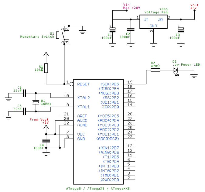
Each buzzer will have the following wireless modules:
You can use any of the port from 6-13 to connect to a buzzer
and light. Also note the ATMEG also need
to be powered and crystal needs to be added
It can be programed using AVR or Arduino if we have the
arduino boot loder insallted
Following is how the power circuit will work

The central controller will have the above circuit. The
logic behind the code should be something like this
1.
Define a structure on how code will be received
from slaves/buzzer. Something like
a.
When key is pressed pass :SL{1}
where ID is a buzzer number and 1 means on
where ID is a buzzer number and 1 means on
2.
The master will look for above patter, while
slaves will ignore the above pattern
3.
As soon as the master receives this, it will
stop looking for more, and transmit a new ACK, something like
a.
:MA{1}
4.
The slave will also monitor for the above
pattern, and master will ignore. Once it receives this pattern, the slave will
check if the ID matches its ID, if it does it will turn ports 6-13 high, which
will turn on the light and buzzer. We can keep the buzzer high for sometime if
we don’t want it to on always
5.
In the master you will coneect an input to one
of the ports 6-13, and when a button is pressed, the whole thing is reset. It
will broadcast something like
a.
:MA{0}:
6.
All slaves will accept the above message and
reset itself and go to sleep
7.
When the button is pressed, the salve will turn
on and go to step 1


